Building a Death Stranding 2-style Voxel 3D Map in Unreal Engine 5
Earlier this year, Kojima Productions’ Ildar Valeev gave a GDC talk called “‘DEATH STRANDING 2’: Making of Voxel 3D UI Map”, walking through how the studio built the game’s map screen: capturing an open-world level, converting it into voxel data, and rendering it back out without any hand-placed artist assets, while staying fast and memory-efficient.
I wanted to see how far the same idea could go in our own UE5 project, for COLDLIGHT’s map screen. This post is the full technical breakdown of what that turned into - the pipeline, the performance work, and a whole category of bugs that only show up after a level save.
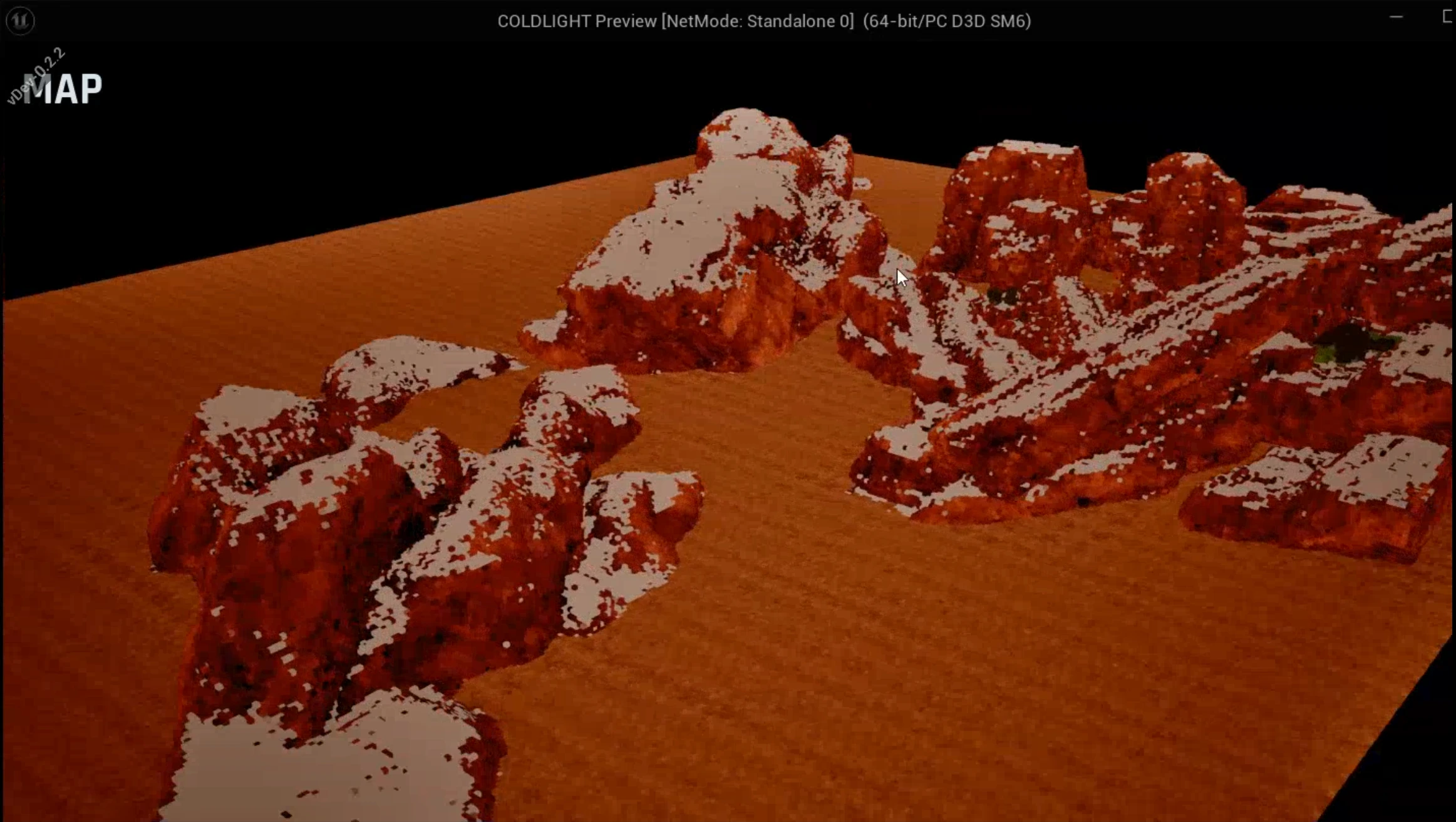
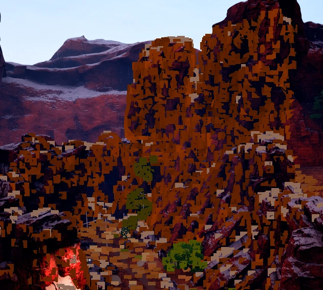
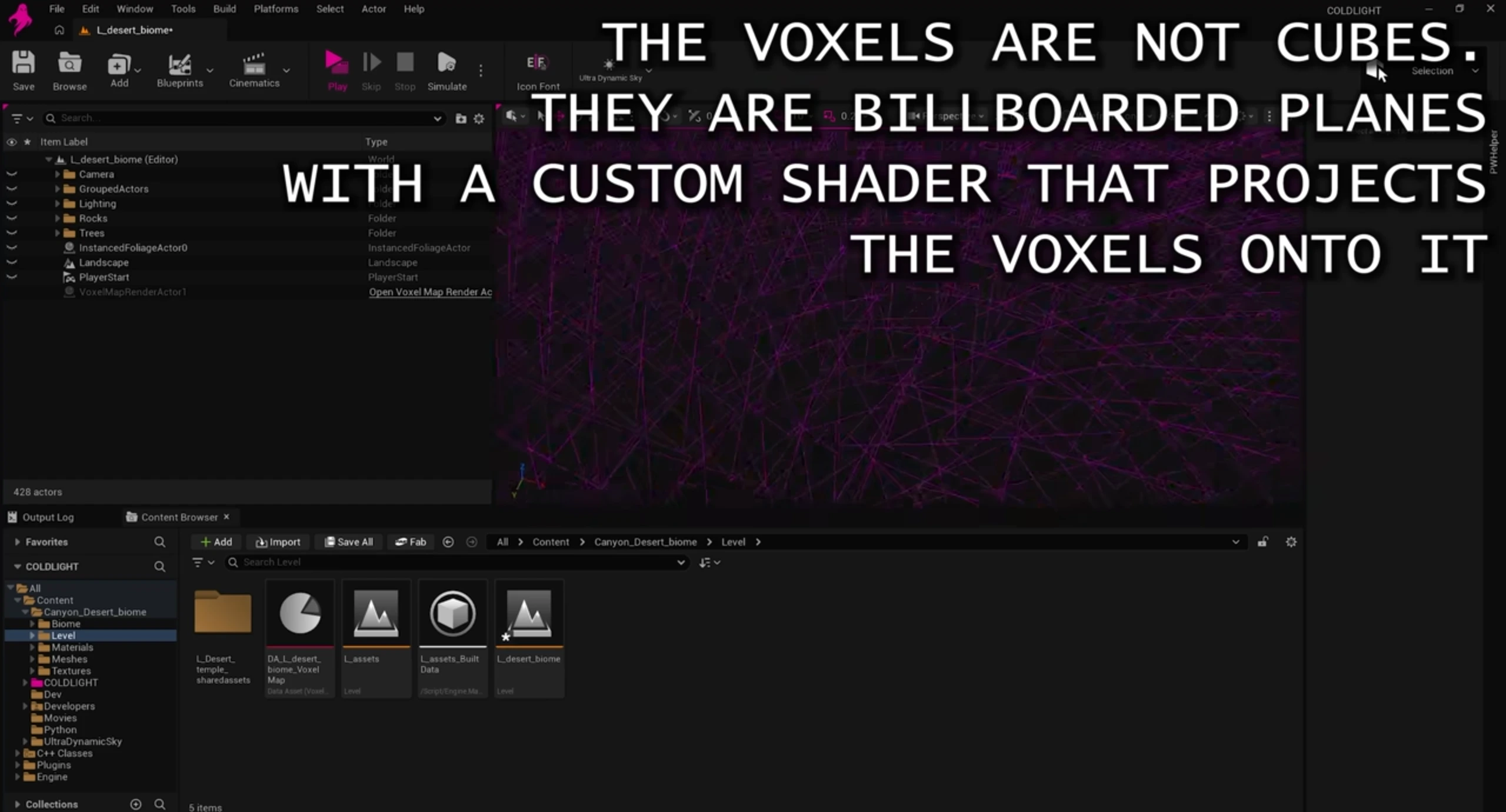
The development screenshots show my COLDLIGHT implementation. The three reference slides below are credited to Ildar Valeev and Kojima Productions’ GDC presentation and illustrate the approach that inspired it. A shorter overview is on the project page.
The high-level pipeline
The system splits cleanly into five phases, plus a UMG integration layer on top:
- Capture - sample the level from a grid of hemisphere and slice views, deduplicate into a voxel grid, and save the result to a self-describing binary file.
- Processing - a visibility flood-fill plus depth-based occluder culling, to discard geometry nothing can ever see.
- Packing - group surviving voxels into 4x4x4 blocks, each carrying Level-1 and Level-2 occupancy bitmasks and a render-data buffer.
- Chunking - group blocks by spatial region, with chunk-relative location indices instead of absolute ones.
- Rendering - bake it all into instanced meshes with a custom ray-box HLSL shader doing the actual per-voxel resolution.
On top of that, a UMG integration layer drives an isolated scene capture with a free-orbiting camera, feeding a map widget the player actually interacts with.
Capture: hemisphere + slice passes
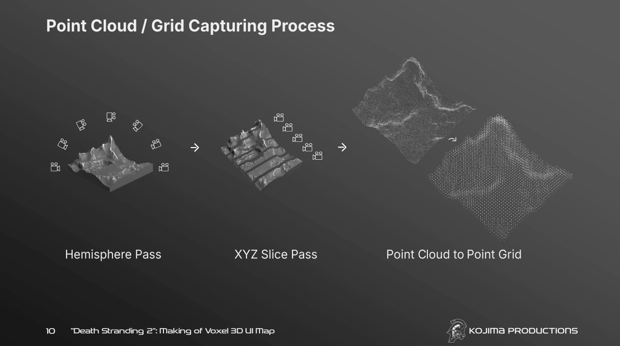
The capture pass samples the level from two kinds of viewpoints - a hemisphere of directional views for broad coverage, and a grid of axis-aligned slice views to catch detail the hemisphere pass misses. Each capture reads depth and colour and unprojects the results into world-space points, which get deduplicated into a voxel grid as they come in.
One early bug here was subtle: SCS_DeviceDepth was quantizing depth reads just enough to introduce real error at range. Switching to SCS_SceneDepth with matrix-free unprojection fixed it outright.
The slice pass was also the single biggest performance win of the whole project, more on that below.
Processing: visibility and occluder culling
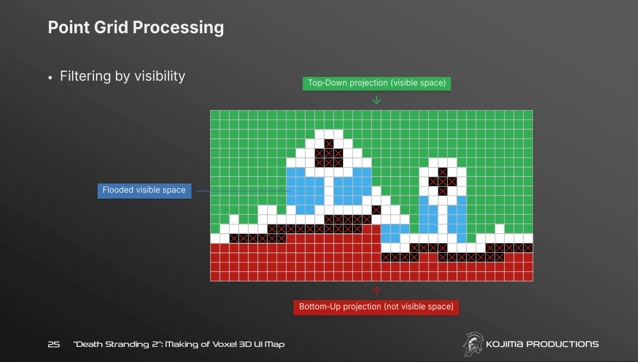
Two culling passes run after capture. A visibility flood-fill removes points that aren’t reachable from open space, and a depth-based occluder culling pass removes points that are provably behind solid geometry from every relevant direction.
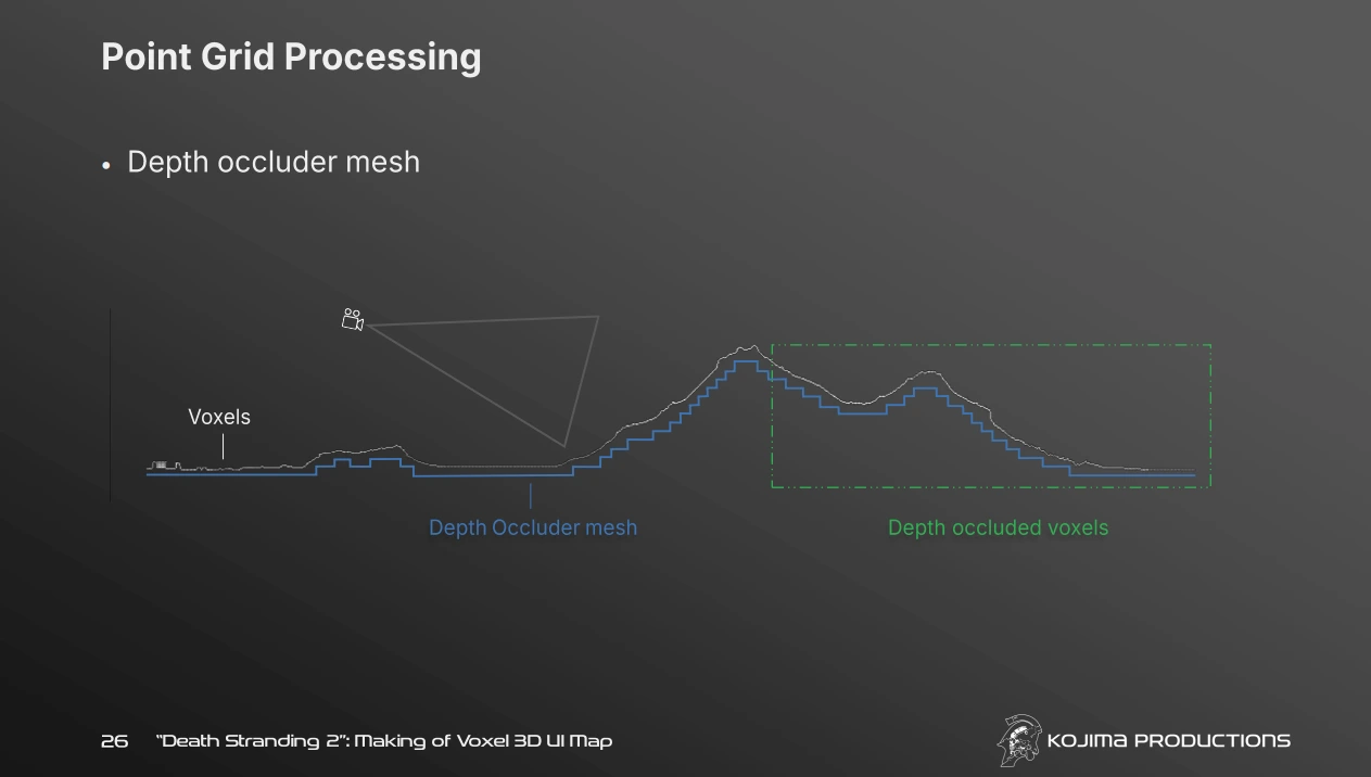
The occluder culling pass went through a real redesign. The first version used a single top-down height map - “is there a higher point in this column?” - which works for most terrain but actively breaks on near-vertical geometry: a point on a cliff face can be the frontmost surface from a side-on view while still not being the topmost point in its column from directly above, so the height-map version was incorrectly stripping large sections of cliff faces. The fix was to make it properly six-directional (top, bottom, and all four horizontal axes), with a configurable minimum number of occluded directions required before a point gets culled. Visually confirmed fixed, and it still meaningfully culls genuinely buried geometry - roughly 20% of points removed post-fix, down from around 50% with the buggy version, at negligible extra cost (about 0.05s for all six directions on top of the existing pipeline).
Packing and chunking
Surviving points get packed into 4x4x4 voxel blocks. Each block stores a 24-bit location index plus two levels of occupancy bitmask - an 8-bit Level-1 mask for 2x2x2 sub-regions, and a 64-bit Level-2 mask for individual voxels - alongside a start index into a render-data buffer holding the actual per-voxel colour data. Blocks then get grouped into spatial chunks, with their location indices re-expressed relative to the chunk’s own local grid rather than the whole capture volume.
This is also where the project picked up its persistent Data Asset boundary: UVoxelMapDataAsset holds the packed chunk data plus the grid-context fields (capture center, grid origin, block world size, and so on) needed to decode block positions back into world space later. Without those fields traveling with the chunks, the packed data alone can’t be turned back into anything meaningful.
Rendering: ray-box voxel shader
Each block becomes one instance on a UHierarchicalInstancedStaticMeshComponent, billboarded and driven by custom material logic doing 4x4x4 DDA stepping through the block’s own occupancy bitmasks - resolving real per-voxel colour and depth per hit, not just showing a flat billboard. Distance-based LOD skips the full per-voxel stepping past a configurable threshold and falls back to a single representative colour for the block, with a dithered transition band instead of a hard pop.
Per-voxel colour data is baked into a runtime lookup texture - one texel per captured voxel - wrapped across a fixed row width rather than using one unbounded row, since a single-row texture wide enough for a large multi-segment capture would blow straight past texture dimension limits.
Getting to production scale
At real scale (a capture volume broken into 4000-unit segments, 64-unit voxels, 128 render resolution), the pipeline needed real performance work, all confirmed against real before/after timing:
- The slice pass was oversampling 4-8x relative to what the geometry actually needed. Tuning slice count and spacing cut slice-pass time roughly 5x, for under 3% coverage loss.
ParallelForon both the per-pixel capture loop and the per-voxel culling loops.- The visibility flood-fill was rewritten from
TSet/TMaphash lookups to denseTBitArraygrids, O(1) indexing instead of hashing, for a 23x speedup on its own. - A per-view line-trace pre-check skips slice views aimed at open air before doing any real capture work.
Altogether, a full per-segment pipeline (hemisphere + slice + visibility filter + occluder culling) went from multiple minutes per segment down to about 1.35 seconds, roughly a 175x improvement end to end. An async, pipelined GPU-readback rewrite was attempted for the slice pass specifically, but hit a genuine runtime hang and got abandoned in favor of the sampling-density fix, which solved the actual problem without the risk of touching RHI-level code.
The instance-count wall: 673K instances and the editor freeze
Once real levels started producing 600K+ voxel block instances, selecting the render actor at all (in the outliner or the viewport) froze the editor solid. This turned out to be two separate problems wearing the same disguise:
- Unreal’s per-instance selection outline system tries to draw a highlight around every single instance when an ISM/HISM component gets selected. At this scale that’s catastrophically expensive, and there’s no legitimate reason to ever select this component by hand: it’s a pure rendering proxy for already-baked data. Setting
bSelectable = falseon the component removes it from the selection system entirely. - Separately,
AddInstanceComponent(needed so the runtime-created component actually saves with the level) implicitly setsRF_Transactional, which means Unreal’s undo/transaction system may snapshot the entire instance transform and custom-data array on any transactable operation that touches the component, a much larger cost than the Details-panel display itself, and the more likely real cause of the original freeze. ClearingRF_Transactionalafter adding the component keeps it saving with the level while excluding it from that snapshotting specifically.
Splitting capture from render
The system started as a single actor doing both authoring-time capture and runtime display. That got split into two: AVoxelMapCaptureActor (capture, processing, packing, chunking - produces a Data Asset, and is only ever needed transiently during a bake) and AVoxelMapRenderActor (consumes already-packed chunk data, builds the renderable instances, and drives the UI’s orbit-camera scene capture - the thing that actually needs to exist in a shipped level). Shared structs and stateless utility functions (packed block/chunk data, the world-position decode function, a couple of bit-manipulation helpers) moved into a common shared module both actors use identically.
This also meant building real editor tooling: a “Build Voxel 3D World” pipeline that spawns a capture actor from a set of project-wide default settings, auto-fits its capture bounds to the level, runs the full segmented capture, converts the result into a Data Asset in the level’s own content folder, then spawns and configures a render actor pointed at it, registered as a proper custom build type through Unreal’s own build system, so it shows up in the native Build menu alongside the engine’s own build steps, with a progress dialog and cancel support.
UI integration: orbit camera and markers
The map itself renders through an isolated SceneCaptureComponent2D restricted to a show-only list containing just the voxel block mesh: nothing else in the level bleeds into the capture. An orbit camera (yaw, pitch, zoom, pan, all independently clamped) feeds that capture, driven by mouse-drag and scroll input in a UMG widget.
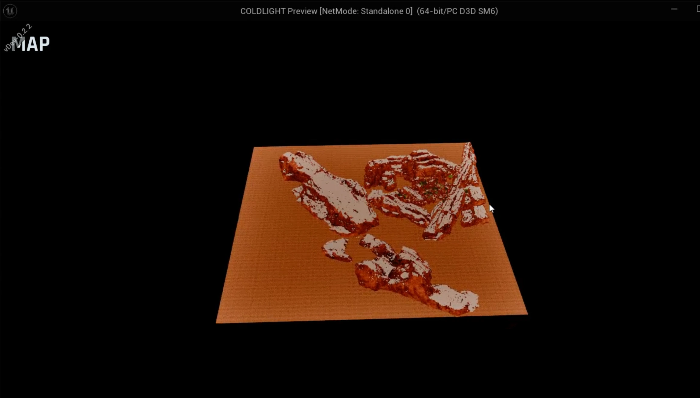
The player’s own representation on the map ended up as two deliberately separate systems, rather than one:
- A 3D player model: a mesh placed directly in the voxel scene at the player’s real-world position, baked into the same scene capture as the voxel blocks. Since block instances are already placed at true absolute world-space positions, the player’s actual location drops straight in with no coordinate remapping needed.
- A set of 2D UI markers: player location, points of interest, objectives, and whatever else comes later, rendered as icons directly in the UMG widget, entirely independent of the 3D scene. Since these markers live in screen space, they need a live projection from world position through the map camera’s actual current view (its live transform and field of view) into normalized screen coordinates, not the player’s own camera, which is a different view entirely. That projection recomputes on every camera move, so markers track correctly through rotate, zoom, and pan, not just on initial placement.
Keeping those two systems independent means a marker can exist without a 3D model and vice versa, and neither has to know anything about how the other is implemented.